


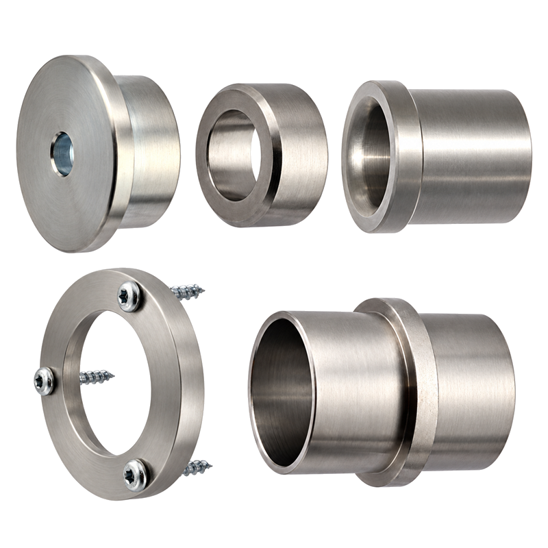
Drilling aid Set with guide sleeve and drill bushes
CHF 325.00
excl. VAT
Drilling aid Set with fixing rosettes, guide sleeve, fixing ring and seven drill bushes for wood, masonry, rebar and brick drill bits.
For accurate drilling in both angle and position using a wooden template.
Drill bits sold separately.
Pack size: 1 Set.
Drilling aid Set with guide sleeve and drill bushes
The LamiFIX drilling aid Set LF 2121.001.4 brings together matching components for drilling stair tread bolt holes accurately in both angle and position using a wooden template.
Supplied components according to the 2026/28 catalogue, page 27
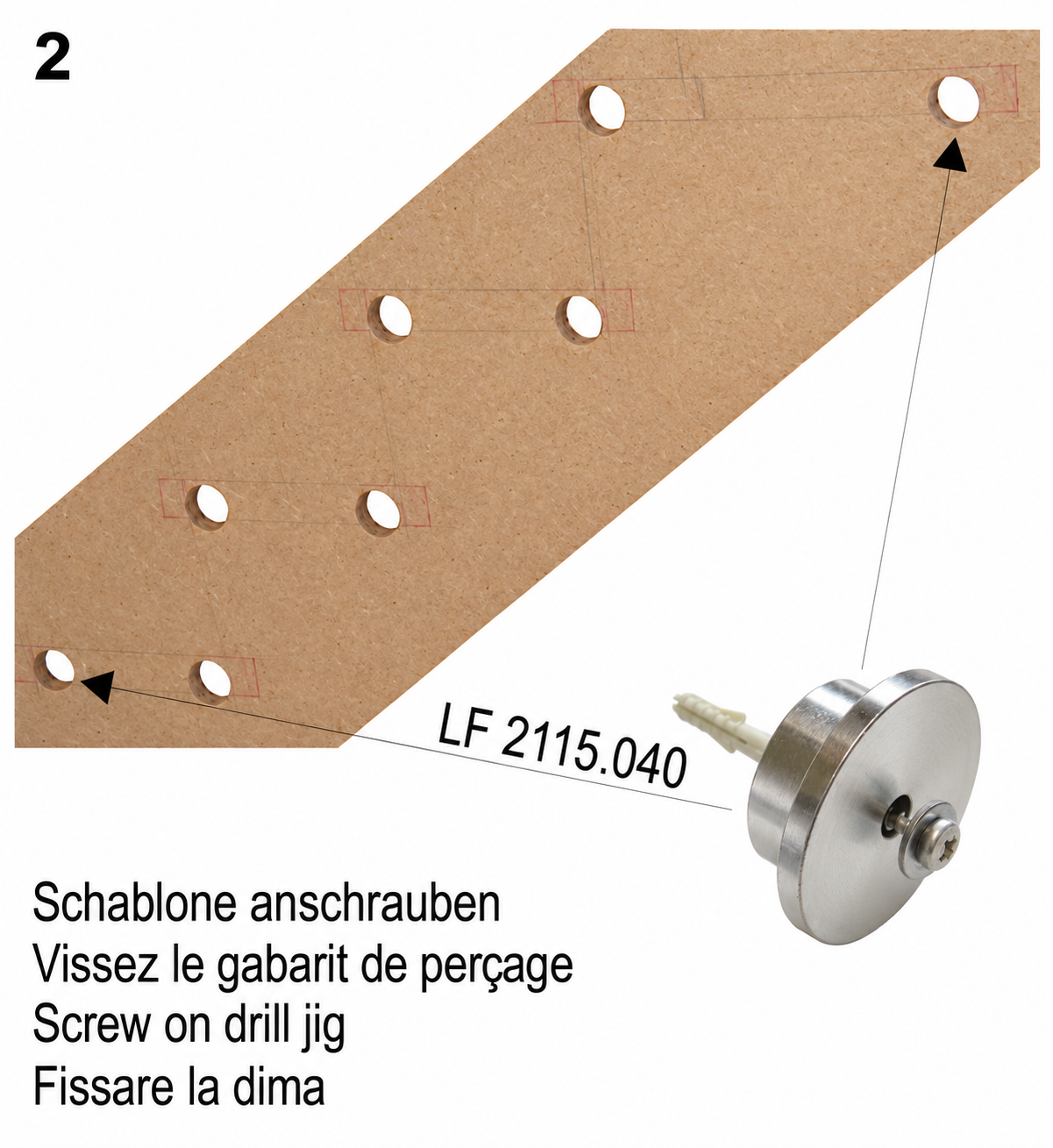
- Ø40 mm zinc-plated steel fixing rosettes with stainless steel centring rings – LF 2115.040.3
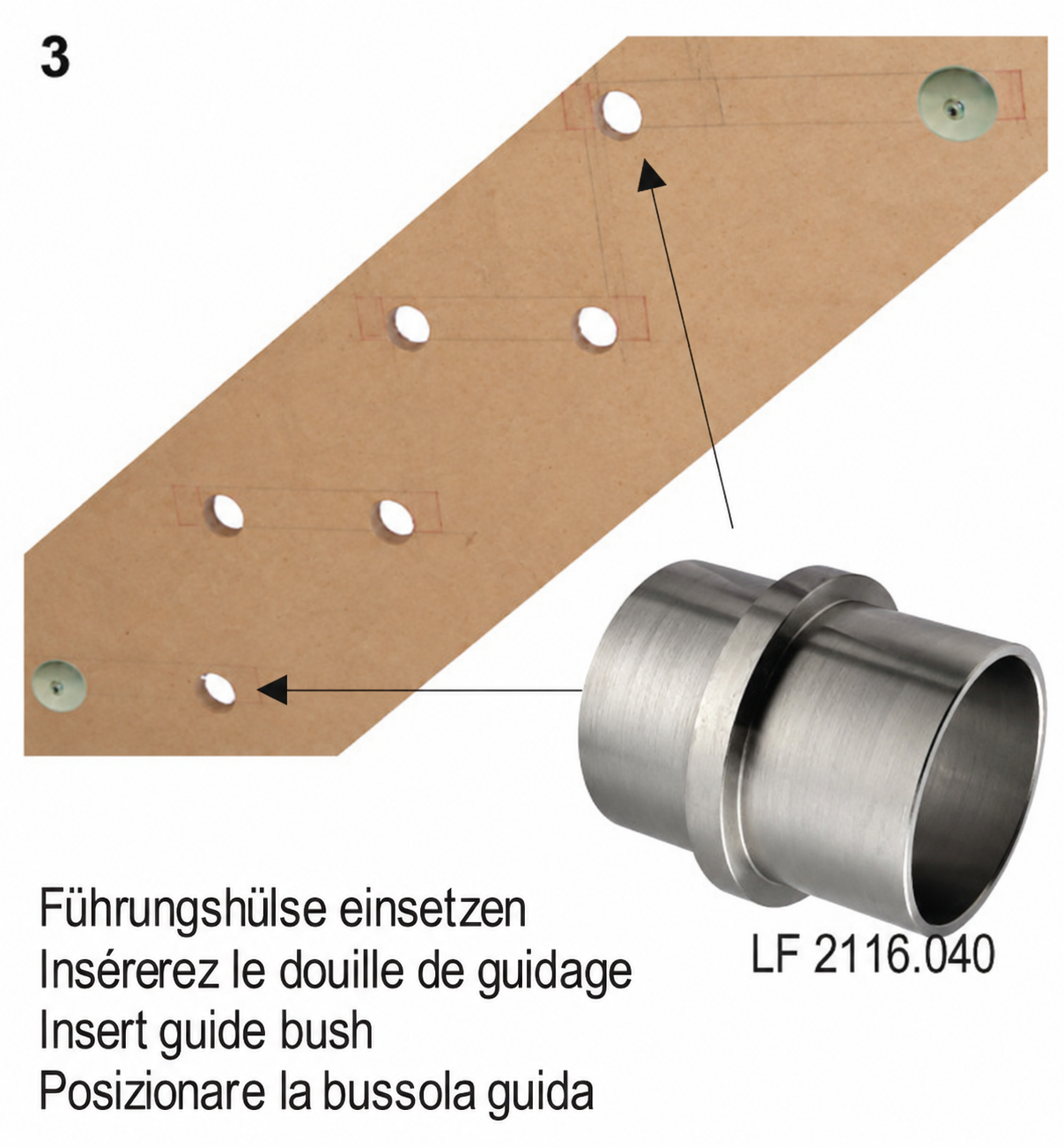
- Guide sleeve for drill bushes – LF 2116.040.3
- Fixing ring for guide sleeve – LF 2117.040.3
- Drill bush for Ø25 mm wood drill bit – LF 2118.250.3
- Drill bushes for Ø16, Ø20 and Ø25 mm masonry drill bits – LF 2119.160.3, LF 2119.200.3 and LF 2119.250.3
- Drill bushes for Ø20 and Ø25 mm rebar drill bits – LF 2120.200.3 and LF 2120.250.3
- Drill bush for Ø32 mm brick drill bit – LF 2120.320.3
Matching drill bits are sold separately. The wooden template is made on site to suit the stair layout.
Pack size: 1 Set.
Drilling accurate holes on site
LamiFIX drill bushes, matching drill bits and guide sleeves allow stair tread bolt holes to be drilled accurately in both position and angle. A purpose-made wooden template defines the hole positions. It is secured at the points where the bolts will later be installed, avoiding additional fixing holes that would need filling after installation.
Step by step
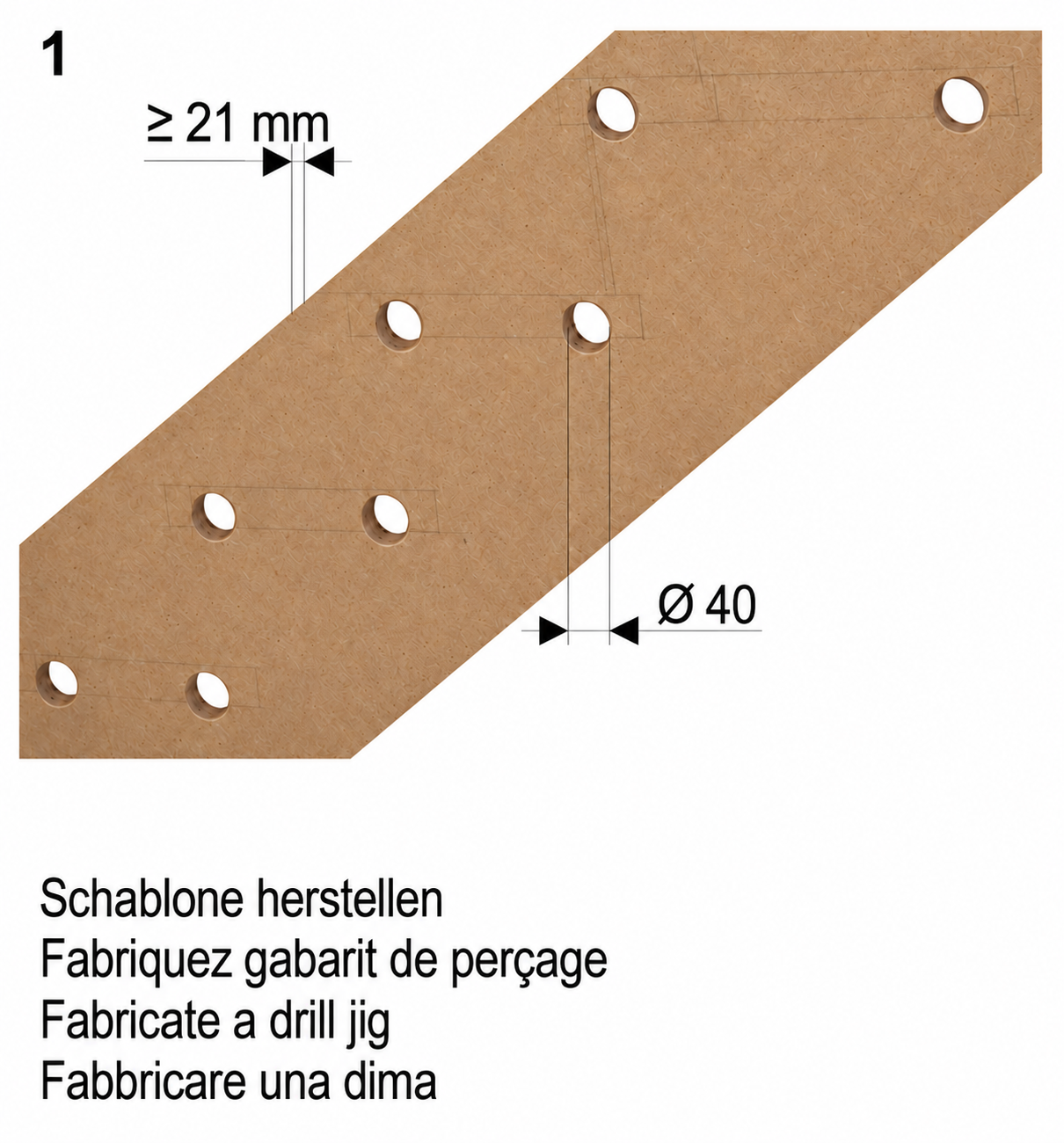
- Make the wooden template – image 1
Use a wooden template at least 21 mm thick. Drill a Ø40 mm hole at each planned stair tread bolt position. - Secure the template – image 2
Screw the template in place at the top and bottom using the zinc-plated steel fixing rosettes LF 2115.040.3. Use positions where stair tread bolt holes will later be drilled. This avoids leaving additional fixing holes in the wall after installation. - Insert the guide sleeve – image 3
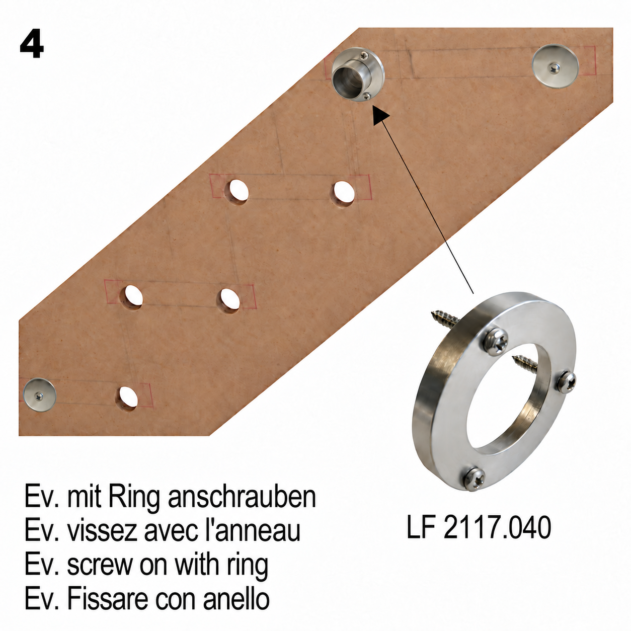
Insert guide sleeve LF 2116.040.3 into the corresponding Ø40 mm hole in the template. - Screw the guide sleeve in place if required – image 4
For hammer drilling, secure the guide sleeve with fixing ring LF 2117.040.3. This holds it in position and keeps the drill bit at the correct angle. Guidance is also maintained when changing from a masonry drill bit to a rebar drill bit. When drilling wood, for example with Sets 1, 2 and 6, simply inserting the guide sleeve is generally sufficient. The drilling mode depends on the wall material and the chosen Set. - Fit the appropriate drill bush – image 5
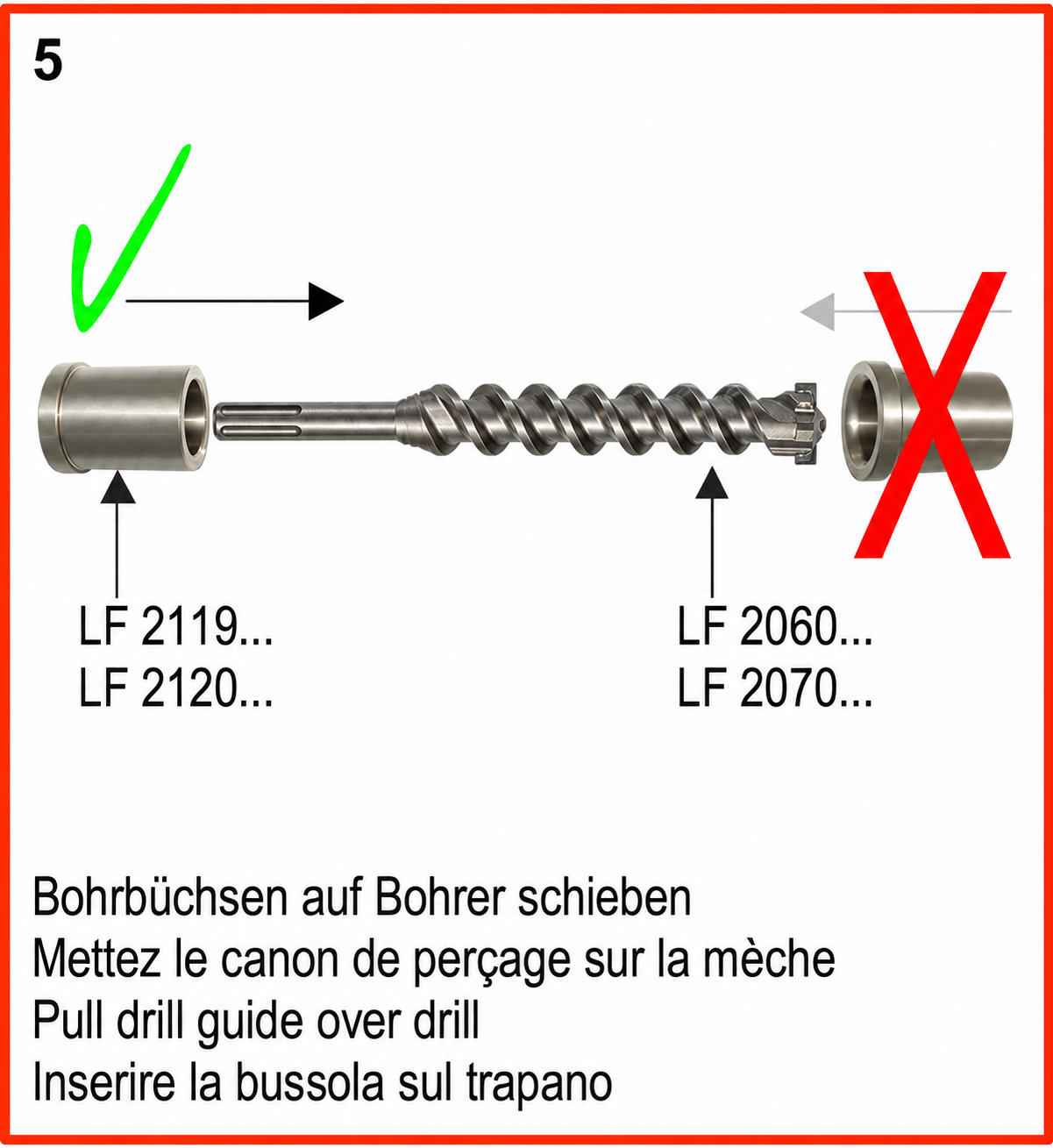
LamiFIX drill bushes for masonry and rebar drill bits are matched to the shank of each bit. They guide the bit accurately at the correct angle throughout the drilling depth. Slide the bush onto the shank from the rear before fitting the bit to the drill. It cannot pass over the wider cutting head. On the matching Ø25 mm wood drill bit, the bush can also be slid over the cutting head. - Drill the accessible holes – image 6
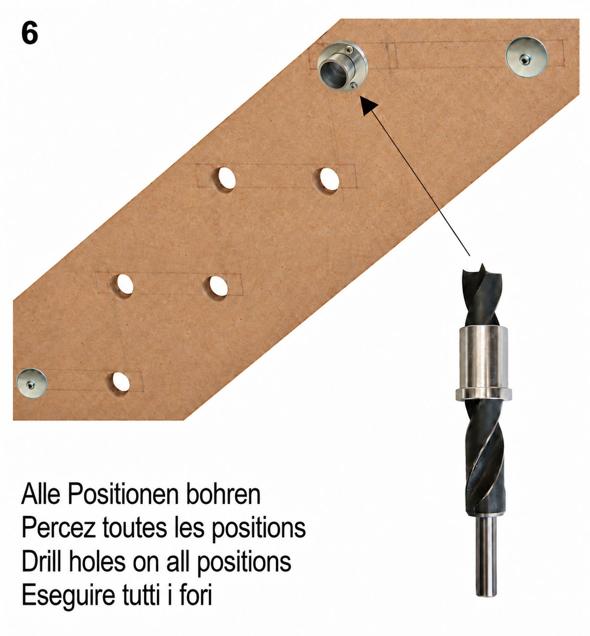
First drill all positions that are not occupied by fixing rosettes. - Install one bolt at the top and one at the bottom – image 7
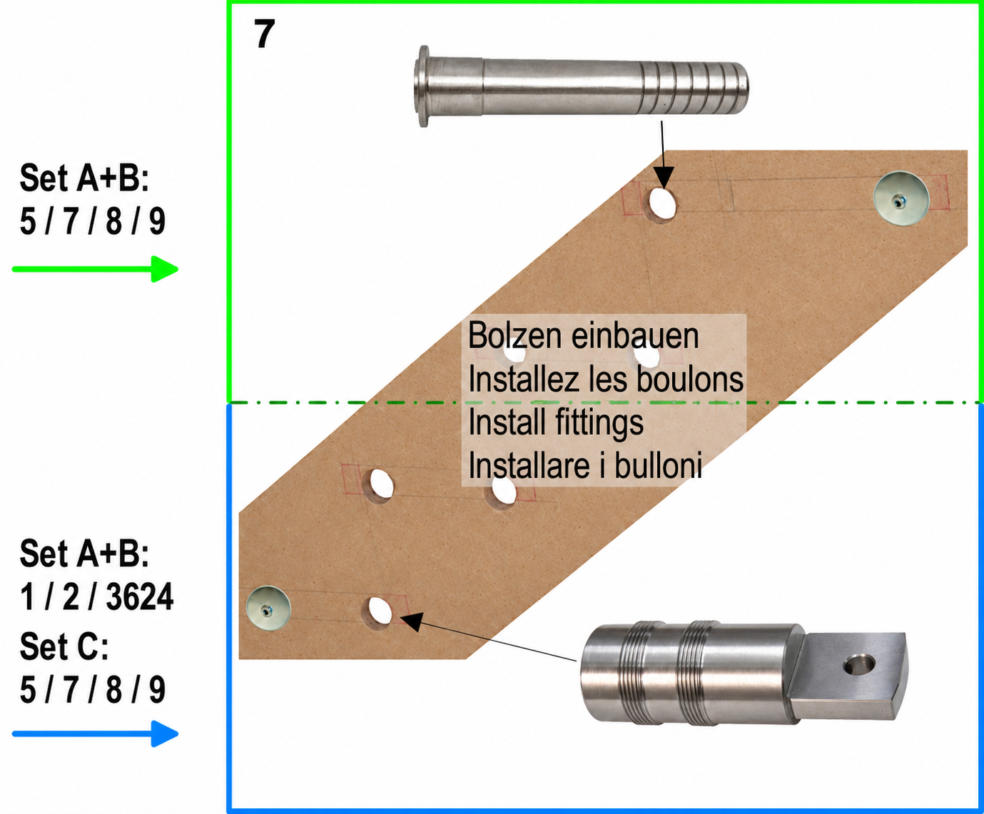
Install a stair tread bolt in an already drilled hole at the top and another at the bottom, following the installation instructions for the chosen Set. - Support the template on the installed bolts – image 8
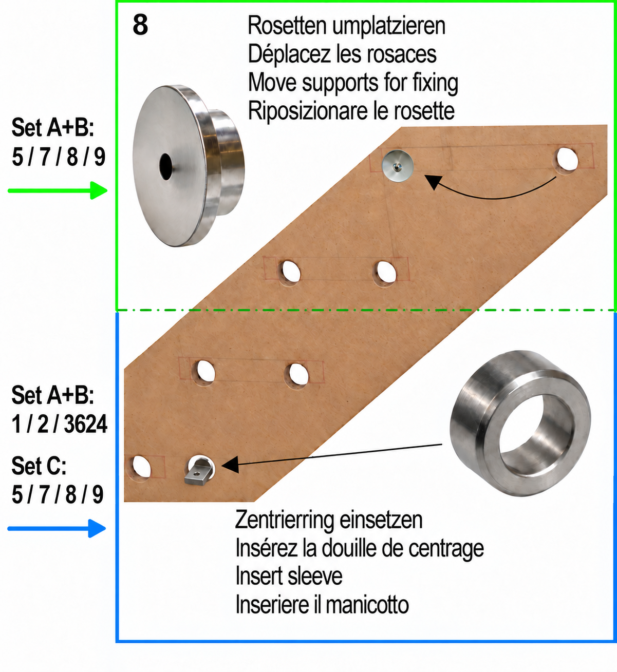
Sets 5, 7, 8 and 9 in version A or B: Reposition the fixing rosettes used previously, as shown in the upper part of the image.
Sets 1, 2 and 3624 in version A or B, and Sets 5, 7, 8 and 9 in version C: Slide the matching stainless steel centring rings onto the installed bolts to hold the wooden template in position. Then remove the original fixing rosettes at the top and bottom. The final drilling positions, previously covered by the rosettes, are now accessible. - Secure the template and drill the remaining holes – image 9
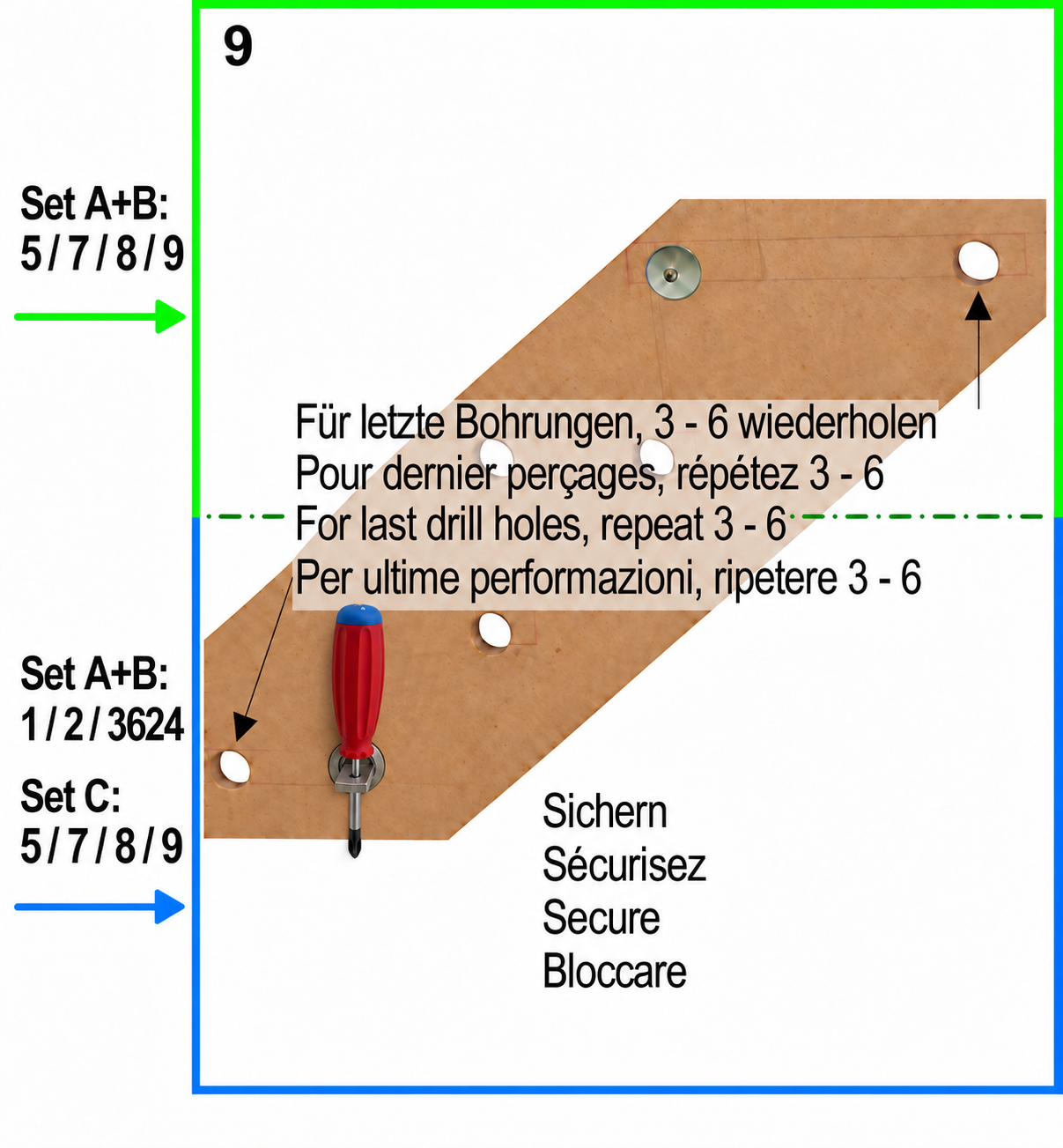
For Sets 1, 2 and 3624 in version A or B, and Sets 5, 7, 8 and 9 in version C, prevent the template from falling by passing a screwdriver through the cross-hole in the bolt. Then drill the remaining holes by repeating steps 3 to 6.
Once these steps are complete, all fixing holes are at the intended bolt positions. No additional holes requiring later filling are needed.
The remaining bolt installation steps are shown in images 10 to 12 of the installation instructions in the LamiFIX 2026/28 catalogue, page 26 . Follow the instructions for the chosen Set.
Additional information
| Fixing substrate |
|---|